Once I had a good idea of the style of locomotive I wanted, I drew up construction plans. This unit is 16' long and 8' wide. For the drive train, I looked to Northwest Shortline (NWSL), and bought their largest 12 volt Pitman motor, universal joints, and worm drives, which fit on my own wheelsets. Online research found Z Battery, a good battery supplier, with many different shapes and capacities of sealed lead acid gel batteries. I wanted the lead acid chemistry for low cost and high weight, and designed for amp-hour capacity of more than 6 hours of continuous running before needing a recharge. I used Shapeways to 3D print bearing blocks, which are fully sprung, and support sealed ball bearings for the drive axles. The radio control system is an Airwire T5000 transmitter with a G3X receiver.
I tried in vain to find brass structural shapes to fabricate the frame. The only place I found wanted a huge minimum order, and had limited shape options. One of my favorite suppliers is McMaster Carr. They sell brass bar stock in many sizes, in lengths as short as one foot. In preparation for construction, I bought a small bench mounted 1" metal belt sander, with a sanding disc on the end. With careful adjustment, I was able to hacksaw my brass stock, and grind square ends, with length accuracy of a few thousands of an inch. In this manner, I was able to fabricate the frame parts out of bar stock, which were soft soldered by torch to become the structural shapes I wanted. If I had used high temperature silver solder, I could have joined the parts together with soft solder, but I chose to bolt things together instead, using 2-25 threaded rod and nuts, which are 1" bolts in my scale.
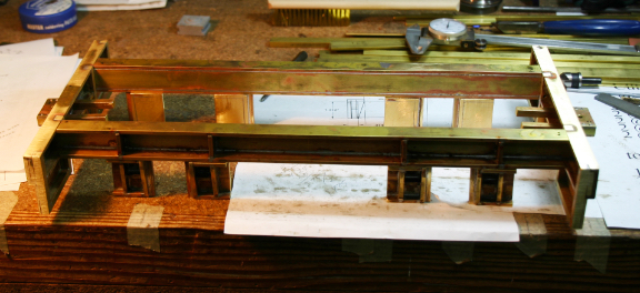
Here is the lower frame under construction.
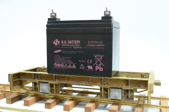
Here is the lower frame further along, with axles in sprung ball bearing blocks and the battery resting in place.
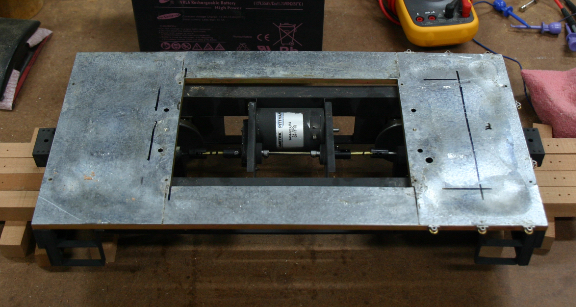
The lower frame consists of two side channels joined to two end beams. Two cross panels support the ends of the motor. Two 1/4" square cross bars secure the inner ends of the coupler pockets, and anchor the radius arms that keep the worm drive units from rotating. Once I got this far, I could run the drive and see how things looked. Even with the lowest gearing from NWSL, I had a top speed of about 30 mph, which was too fast. This kind of prototype ran slowly, and I expect to have a little over a mile of track, so there was no need to rush. I decided to rebuild the cross panels to mount the motor off the centerline, and used sprockets and Delrin drive chain from Micro Mark to create a 2:1 reduction, for a top speed of 15 mph. This required a central drive shaft, supported on bearings, and a cover plate to protect the drive chain from debris. At this point I disassembled everything and painted it all with flat black Rustoleum primer.
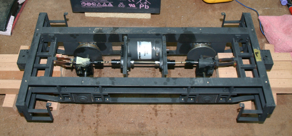
Here is the painted and assembled drive train.
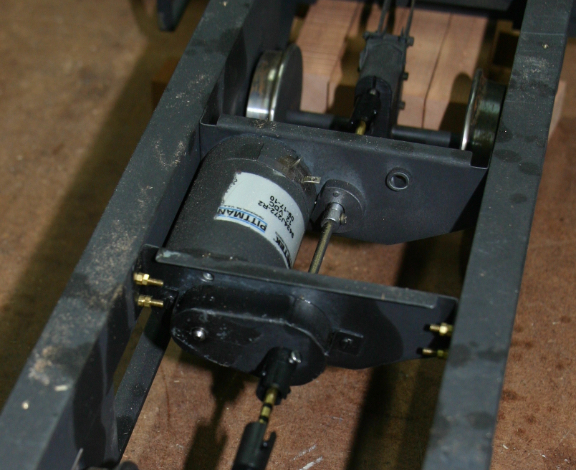
Here are the details of drive chain reducer, central shaft and bearings.
The locomotive was built with a lower frame holding the drive train, and an upper frame which would secure the battery, mount the radio control electronics, and support the decorative shell with detail parts. The upper frame of 1/4" square bar stock was soldered to a piece of sheet metal for the deck. Handrail supports were soldered to this frame, allowing the hand rails to be painted separately, but attached securely.
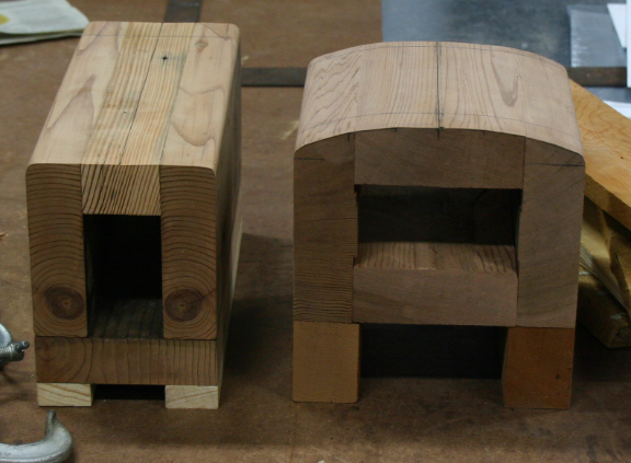
The shell of the locomotive was constructed of .060" sheet styrene. I like working in styrene for modeling metal sheet, and it had the advantage of not blocking reception for the radio receiver of the control system. I made forms to bend the styrene over, using a heat gun designed for stripping paint. It took a few trials to get my heating technique perfected, warm enough to get the smooth bend I desired, but not so hot it deformed or charred the plastic. I used pieces that were larger than I needed, expecting to trim them. Here are the two bending forms.
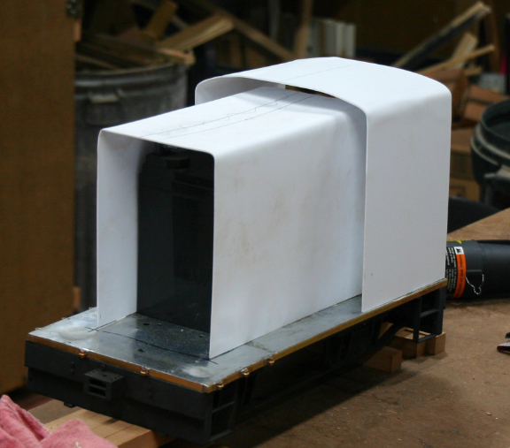
Here are the two bent and trimmed pieces sitting on the deck.
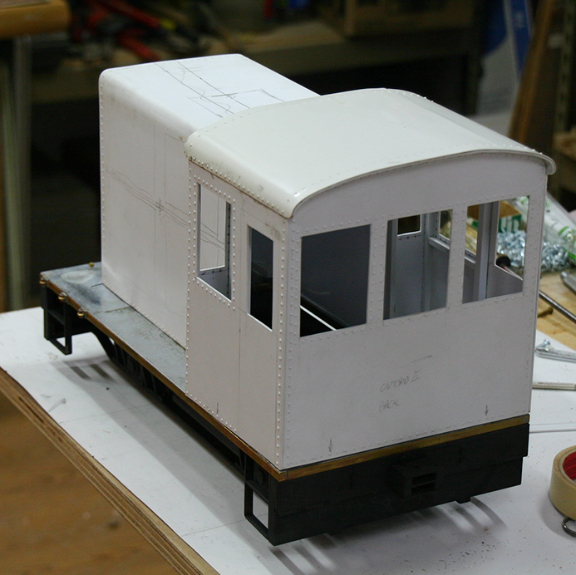
Once the two large pieces were bent and trimmed, I cut the front, middle and back cross panels. The joints are supposed to be riveted together. I used a Micro Mark riveter, with a large rivet die I turned, and dimpled the .060" styrene along all the edge seams. To hold the sheet styrene flat, each joint of the shell, and the lower edges, are braced internally with 1/4" square styrene strips, and the windows were braced with 3/16" square strips. Another piece of .060" sheet, with the edges riveted, was cemented to the roof with contact cement. Here is the assembled shell.
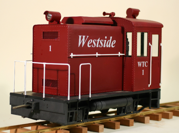
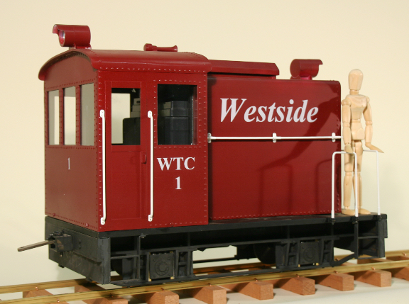
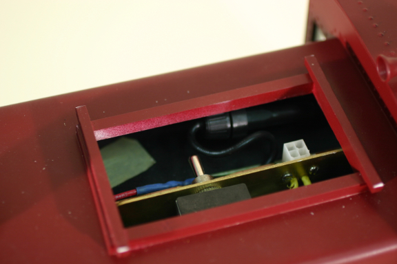
The rest of the construction was finishing the details. The handrails were fabricated from 3/32" brazing rod. The joints were beefed up with short pieces of brass tubing to resemble fittings, and everything was soldered together. The deck handrails dropped into the fittings attached to the upper frame. The horizontal handrails had mounting pads with wires soldered on to allow them to be attached to the shell after painting. The vertical handrails beside the doors also had mounting pads, but were designed to be attached with small escutcheon pins after painting. The headlight and backup light are turned from 1" PVC pipe stock, with Maglite reflectors and LED bulbs. The air horn is turned aluminum rod. The hatch on the top of the shell is an air vent to cool the battery and control electronics, as are the mesh panels in the front end. The hatch cover lifts off for access to the main on-off-charge switch, an inline fuse, and the battery recharging plug. I had custom decals made by Ricky Rupp at Modern Rails Decals. The shell was painted with Rustoleum, and the window glass pieces were secured with silicone caulk. I am pleased with the final result.
The top hatch is removed, showing the power switch and charging plug.
The finished locomotive weighs almost 42 pounds, and the drive train is robust enough to slip the drivers with a tractive effort of 10.5 pounds on level track. I built a test ramp to see what kind of grade I could pull. While the locomotive couldn't pull three loaded log cars up a 10% grade, it could manage an 8% grade. That became my ruling grade for the railroad. I did a careful survey of my property, and found that I can create a track plan that gets me where I want to go with an 8% grade limit.
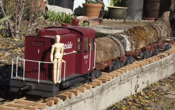
Here is a shot of WTC1 and a load of logs. This was a beauty shot made before any real track had been laid.
Realistically, this railroad construction project will be long term. I will eventually have a storage area in the basement with access to the outdoors, allowing equipment to stay on rails, ready for easy operation, but that is future tense right now. Now that I have a locomotive, I can begin serious construction of track and roadbed. I have some retaining walls to build first, so it will be a while before much track is actually installed.