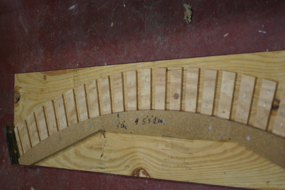
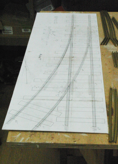
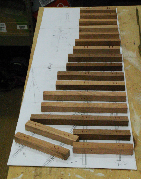
Building switches is much more complicated. I started by drawing a #3 switch in my drafting program, and printing it out full size, both left and right, and then glue the result to a piece of matt board.
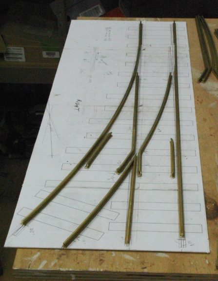
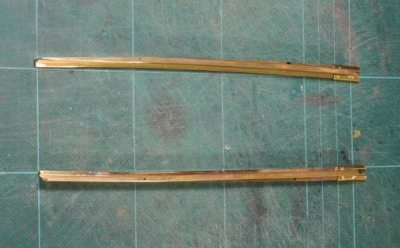
After making the first switch, I had a cutting list and bending templates, so all the rail parts are cut to length and bent to shape, using the rail bender as needed, and a vise. Here all the pieces are laid out on the template for shape verification.
The stock rails are marked for the cutouts where the points fit, and ground to shape with a bench belt sander and finished with files.
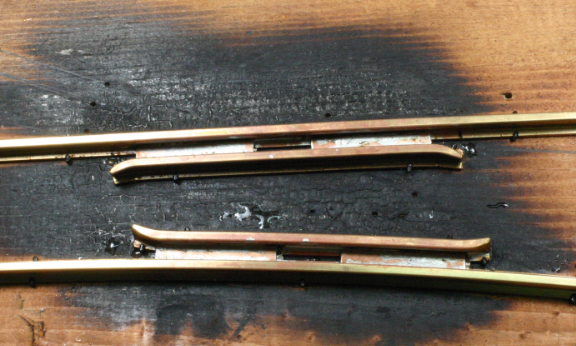
The frog is soldered together. The #3 layout is drawn on a pine board, and the rail pieces spiked in place. Short piece of copper wire are placed in the flangeways so the resulting soldered assembly will has the proper flange clearance.
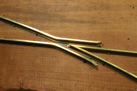
A torch is used to heat everything, and solder is applied. Small pieces of sheet copper have been dropped into the flangeways and soldered in, to give more strength to the frog assembly.
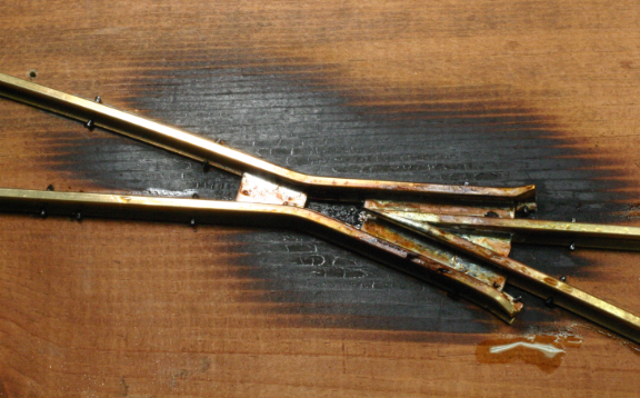
The same basic process is used to solder the guard rails to the stock rails.
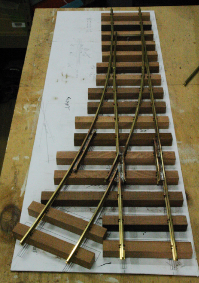
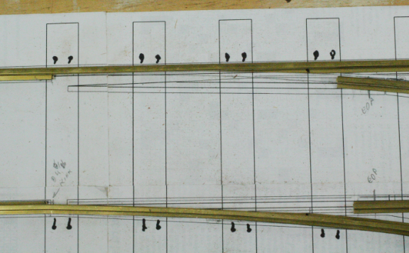
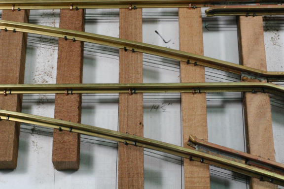
Using a cutting list for the long switch ties, and adding enough "regular" ties, a full set is placed on the template, and then all the rail pieces, except the points, are laid in, ready for assembly.
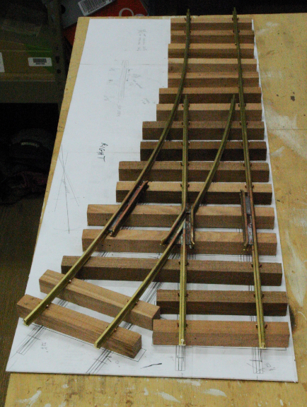
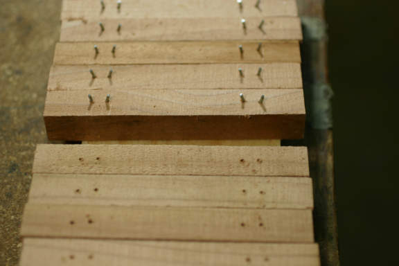
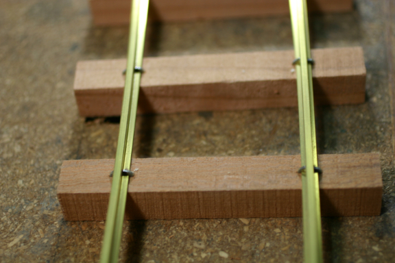
All the "regular" ties with staples get crimped to the rail, and everywhere else is spiked with 1/2" "G" scale spikes. On the more recent switches, I have drilled holes and adding steel staples where possible, giving more strength to the resulting switch. Here is the switch almost finished.
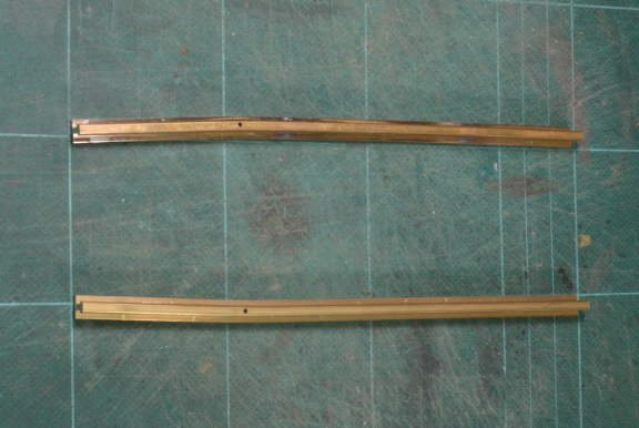
The points are first bent to lay into the stock rails, and then the extra material is ground away with the belt sander. A short piece of rail joiner is crimped to the end of each point to act as pivot hinges.
Each point has a tab soldered near the thin end. A 2-56 screw attaches each point to the tie bar, allowing sufficient flange clearance. An over center spring hold the points to one side or the other.
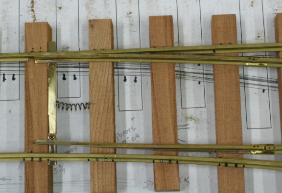
Here is a finished switch ready to be installed.