Part 1. Making A Track Gauge
The building of a switch requires some decisions be made about track gauges. In the smaller scales, the NMRA has settled this issue and a gauge can be purchased. In HO, this all purpose gauge sets track width maximum and minimum, flange-way width minimums, and wheel flange depth, width, maximum outside spacing, and minimum back to back spacing. These relationships are critical to a proper performance of track and switches.
In the large scales used outdoors, there is no common definition of these dimensions. I understand that a group is working to establish large scale gauge standards, but nothing is final yet. Most stock wheel sets will tolerate a relatively wide range of the actual gauge of track. However, in switches, there are two important problem areas, the frog and the points.
In the frog area, the critical dimensions are the opening of the flange-ways and the back to back spacing between the guard rails and the wing rails. The flange-ways must be wide enough to allow the maximum wheel flange width to pass through without binding. The guard rail/wing rail spacing must be wide enough to keep a wheel flange from picking the point of the frog, but not so wide that it binds the minimum back to back dimension of the wheels. This dimension is related to the wheel flange spacing maximum and minimum.
In the point area, the problem is the spacing between the tips of the points. This spacing affects how far the points throw, which wants to be a minimum, but must be far enough that the narrowest wheel flange spacing will not pick the open point as it rolls through.
When I first started building switches over ten years ago, I decided to build my own gauge by scaling up the dimensions from an NMRA HO track gauge. This has worked well over the years, since all of my equipment is set to the same dimensions, and therefore runs properly on my own track. The problems come when other people operate on my railroad, or when I take equipment to run elsewhere.
I made a gauge out of a square of 1/6" sheet brass. I simply filed the shapes I wanted, checking the final dimensions with a pair of calipers. Whatever standards you choose to use, a gauge is essential to the proper construction of a switch. Here are the dimensions I finally settled on.
Part 2. Tools
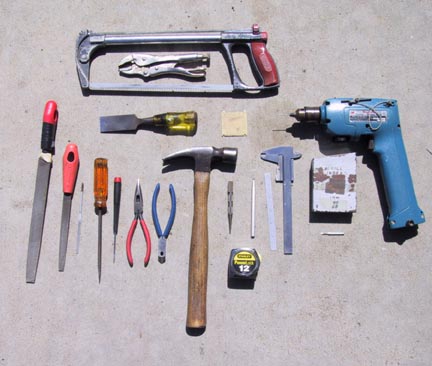
A few basic tools, supplemented by several specialized tools, are required to build a switch. The basic tools are:
fine toothed hacksaw
vise-grip pliers
wood chisel
track gauge (see above)
large flat file
small flat file
flat needle file
flat screwdriver
fine screwdriver
medium needle nose pliers
flush cut rail nippers
smooth face hammer
medium nail set
metal scribe
6" metal ruler
12 foot tape measure
battery power drill
pair of calipers
set of number drill bits
2-56 tap
A bench vise and a bench grinding wheel are the only other tools needed.
Part 3. Making A Frog
The first part to build in a switch is the frog. A frog is usually defined by a number. This is a ratio of the diverging angle. In the beginning, I decided that the minimum radius on my railroad would be 8'. A tangent to this radius generates a frog angle of #5, a ratio of 1:5.
This layout will be used as a guide for fabricating the frog. Draw the layout on a piece of soft pine. Make sure that the board is flat. The finished pieces are spiked to the board before soldering.
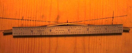
I build my frogs out of nickel silver, because it solders well. The rest of the switch is made from aluminum rail. Three pieces of code 250 nickel silver rail are cut, one is 7" long and the other two are 3-3/4" long. File the ends square and clean, and remove all burrs at this time. The 7" piece will become the point of the frog, and the other two pieces become the wing rails. Mark the center of the 7" piece and bend it to exactly match the obtuse, outside angle defined in the Theoretical Frog Layout.
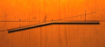
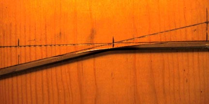
Grind away material to fold this piece of rail to create the point of the frog. A straight edge is used to mark the area to be removed. This line perpendicular to the bisect of the #5 angle, and removes almost the entire head of the rail at the point of the bend.
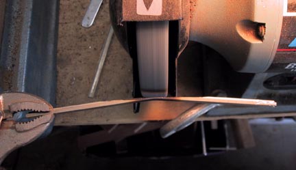
During the grinding process, I use vise grips and pliers to hold the rail while running against a coarse grinding wheel. A bucket of water is handy to quench the hot rail.
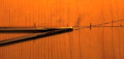
Carefully file off the rough burrs resulting from the grinding process. Break all the edges before folding the rail.
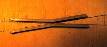
Now fold the rail back on itself. Check to make sure that the base of both legs of the frog sit flat. A little bending and twisting might be needed.
The two shorter pieces of rail are bent to the same obtuse angle, with the bend point 2" from one end. The 2" half will become the wings of the frog. Make a left and right side. Take your time to make sure that the pieces exactly match the theoretical lines. The last 1/4" of the 2" leg is bent out slightly, and the corner tip of the head of the rail is filed off at an angle. This provides the lead into the frog.
Place the three parts and check alignment before spiking down for soldering.
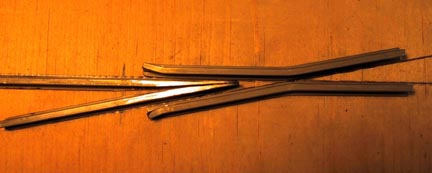
Start with the folded point of the frog. Spike one leg along the theoretical line, then adjust the frog arms and spike the other side. Each of the wing rail pieces are spiked in place one at a time. Spike the short end of the wing rail in place first, then slide the piece until the gap between the wing and the frog point is correctly gauged. I use a gap of 0.118". I have found that a short piece of 0.025" copper wire laid between the webs of the two pieces of rail gives the correct gap. It also gives something for the solder to flow around.
Sight along the rail heads to make sure that the alignment is straight through the frog, from the point of the frog to the wing rail. For strength, I add two small triangular gussets made of 0.020" copper sheet. One is cut to fit into the point of the frog, and the other bridges the two wing rails.
I use a commercial plumbing flux and solder. Make sure the flux is liberally applied between the pieces of rail, and under the copper gussets. I use a small propane torch to heat the metal and apply the solder. Don't worry about burning the pine board.
Remove the frog from the board, and clean it up with a wire wheel or brush. File the bottom and top surfaces flat. Check the gauge on the wing rails, and open the gap with a file, if necessary. The frog is finished frog, ready to build a switch.
Part 4. Laying The Switch
The first step to laying a switch is to decide on the hand of the switch (right or left). Also determine to which side the long switch ties extend (straight side or curved side). These are the ties that support the switch throw.
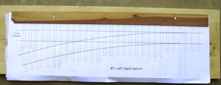
Below are full size templates upon which a switch can be constructed. I am unable to insure that these will scale out correctly on your printer output. However if you print all the pages, and then take them to a copier which can adjust magnification, these will work. Just make sure that the tie spacing works out to 1" center to center, with the shortest ties 4" long
Right Hand Switch Template (Page 1, Page 2, Page 3, Page 4)
Left Hand Switch Template (Page 1, Page 2, Page 3, Page 4)
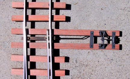
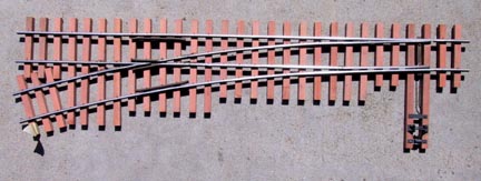
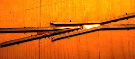
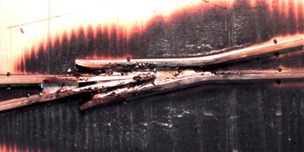
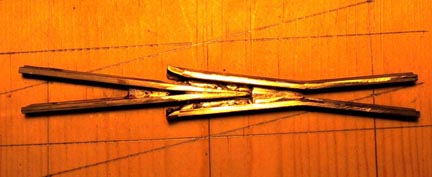
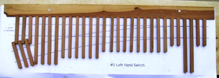
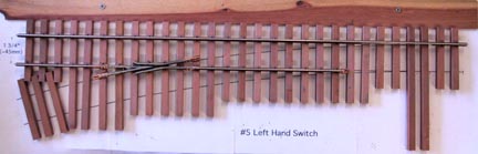
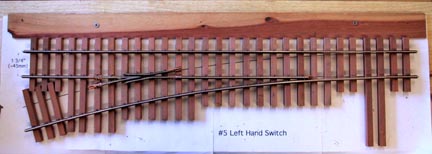
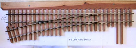
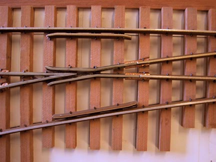
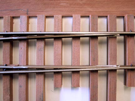
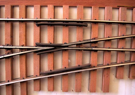
The photos show the construction of a left hand switch with the long ties extending on the curve side. The tie layout template is taped down and a straight edge guide strip is screwed down to aid in placing the ties.
I cut my ties from the best quality redwood I can find. "They don't make them like they used to". I make them 13/64" square. Build a switch with the following set of tie lengths: 10 @ 4", 10 @ 5", 6 @ 6", 4 @ 7", and 2 @ 8" for the switch throw ties. Carefully select which side is to be up. I like to show the tightest grain on top, which weathers to a nice pattern, but that is the weaker orientation to spike through wood, so test it first.
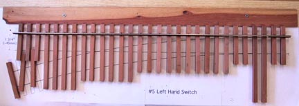
I use code 250 aluminum rail that is already painted. Cut two length of rail 29-1/2", for the stock rails. These are the outside rails on the switch. Hold the rail by the head in a bench vise, mark the length on the bottom with a scribe, and cut with a fine tooth hacksaw. Whenever a piece of rail is cut for use, square the ends with a large file, and de-burr all the edges and corners with a smaller file.
An area on the inside of the stock rails is cutout to make room for the points to fit. Carefully mark the inside base flange at 2-3/8", 4" and 7" from the end of each of the stock rails, at the point end of the switch. With a grinding wheel (or a file), totally remove the base flange between the 2-3/8" and 4" marks. Grind flush with the central rail web, without touching the inside of the rail head. From the 4" to 7" marks, taper the cutout to nothing at the 7" end. With a file, de-burr the cut out area, break all the edges, and then straighten the rail, if needed.
The straight stock rail is spiked down first. Spikes are first placed with large needle nosed pliers, and are driven home with a hammer and a nail set. Use the template to guide the placement of the rail relative to the end of the ties (1" from the end of the tie to the outside of the rail base flange). Make sure that there is 1/2" of rail overhanging beyond the last tie at the point end (trailing end) of the switch. Spike the two 4" ties at the end, and then skip to the 3rd 5" tie to begin spiking again. I first spike every fourth tie, to get the basic alignment established, and then fill in spiking every tie. Make sure that the ties are spaced correctly on the layout template. Eyeball the rail as you work, making sure it is still straight. The rail at the diverging end should overhang the last tie by 1/2".
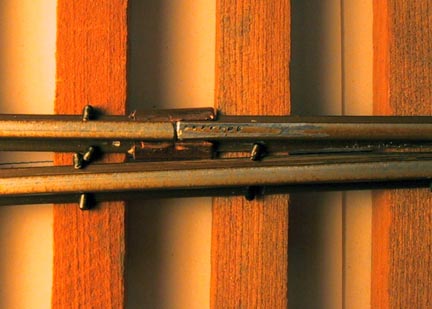
Select the frog, and slightly bend the curved side. Add rail joiners on each of the four rail ends. (I make my own rail joiners from copper sheet, bent over a piece of nickel silver rail. 1/8" x 1/4" brass channel can be used as well.) Place the frog on the ties. The actual tip of the frog should be 18" from the trailing edge of the last switch throw tie. Use a track gauge to set the frog in the correct location. Mark where the rail joiners fall on the ties. With a sharp chisel, remove a thin flake of tie where the joiners sit. Spike the frog down, using the track gauge often to check progress.
Using a square, measure and cut a piece of rail to extend the straight diverging leg of the frog, so that the rail ends of the straight track are flush. Measure and cut another piece of rail for the straight closure rail, which extends from the frog to half way between the 2nd and 3rd 5" ties. Put 1/2 of a rail joiner on this end. Spike the rail in place using the track gauge. Eyeball your progress to make sure the rail is straight.
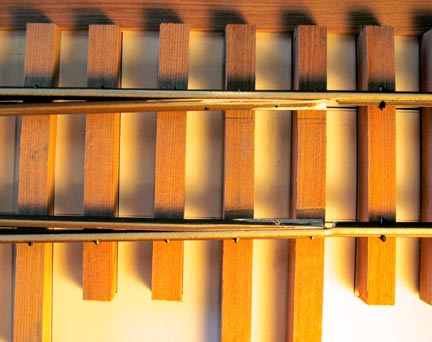
The curved stock rail will be slightly stepped where the end of the point fits. This kink should be at the trailing end of the flange cutout.
Start spiking the curved stock rail at the two 4" trailing ties. Use a square to make sure that the rail ends are flush. At the 3rd 5" tie, push the stock rail against the straight closure rail, and spike in place. Spike the stock rail in the area of the frog, using the track gauge. Gently curve the remaining un-spiked rail, and spike in place. Eyeball your progress to make sure that the rail flows through the curve. Make sure that the rail overhangs the last tie by 1/2".
Measure and cut a piece of rail to complete the curved side of the frog. Make the rail ends square with each other. Measure and cut the curved closure rail. Put 1/2 of a rail joiner on end near the points Spike these pieces down using the track gauge.
On the outside of the stock rail base flange, mark the center of the 6 ties that are not spiked. Move the ties out of way, and drill a 0.052" dia. hole (#55 drill) on these marks, next to the central web of the rail. Replace the ties in their correct location and drive a spike through each of the holes, with the spike head facing out.
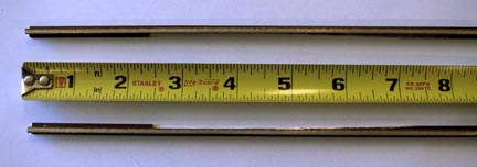
Cut two pieces of rail 3-1/2" long. These will be guard
rails. Slightly flare the last quarter inch on each end. File
the corner of the rail head at the end of each flare.
Place each guard rail with the ends flush with the diverging wings
of the frog. Mark the location of the spikes holding the stock
rail. With a needle file, make a notch to clear each spike head.
Use the track gauge to set the flange-way gap, and spike down
the guard rail. Repeat for the second guard rail.
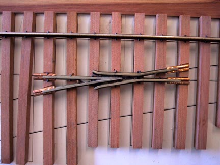
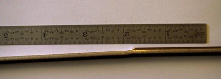
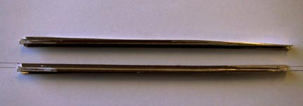
Measure and cut two pieces of rail for the points. They should extend from the end of the closure rails to the outside of the last long switch tie. Make a left and right point. Mark 1-3/4" from the end of the point, and slightly bend the rail inward so that the tip is offset 2/3 of the width of the rail head.
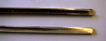
Use the grinding wheel to remove the outside of the point from the tip to the bend. Remove material flush to the center rail web. Extend the flat as a taper toward the hinge end of the point. Clean up the ground area with a large file, breaking all the edges.
Carefully grind the inside rail head from the tip of the point. Remove material so that the inside rail head edge is straight along the length of the point. The tip is feathered to a sharp edge. Make sure that the inside base flange is untouched. Clean up the ground surface with a file. The upper corner of the point tip is beveled slightly.
Check the fit of the points against the stock rails. Make sure that the points lay flat on the ties, without any binding or springing. Adjust the hinge rail joints as needed.
Centered on the 2nd 5" tie, mark the outside flange of each point. File a small notch in each point to clear a spike head. With the point in place against it's stock rail, place a spike in the notch, with the head facing the stock rail. The notch and spike prevent each point from moving away from the ends of the closure rails.
Mark the inside flange of each point in the center of the space between the long switch throw ties. Drill an 0.052" dia. hole as close to the rail web as possible.
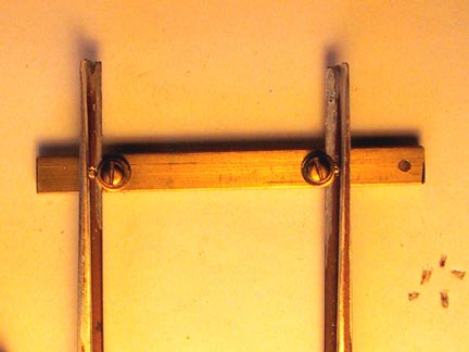
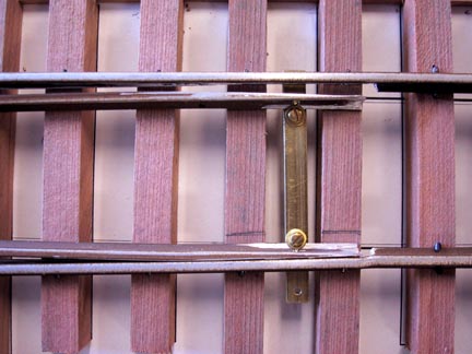
Make a tie bar 1/8" x 1/4" x 2-1/2" long, from brass bar stock. File ends square and flush. Drill 5/64" dia. hole, centered on the bar, 1/8" from one end. This is for the switch throw connecting rod.
Place tie bar in location, using a shim to hold the tie bar up against the bottom of the rails. The end with the hole should be toward the long end of the ties. Position the tie bar in the center of the tie spacing, with the non-hole end flush to the outside of the stock rail. Press the point near the hole end against the stock rail, and mark the tie bar where the point flange hole is located. Remove the tie bar and drill an 0.052" dia. hole through the tie bar. Take an 0.050" dia. brass escutcheon pin, slightly flatten the pin body below the head, and drive the pin into the tie bar from the underside. Clip the pin to about 1/8" exposure. Fit the point over the pin and trim the pin flush with the top of the rail base flange.
Replace the tie bar in the switch, with the first point located on the pin, and pushed against it's stock rail. The spacing of the second point is determined using the gauge, and the flange hole in the second point is marked on the tie bar. Remove the tie bar, drill a second hole and drive in a second escutcheon pin. Trim this pin as before. Replace the tie bar, and check to make sure that the point to point clearance is correct. Mark the area of the switch ties that is covered with the points. Mark the tie bar 0.040" from the inside of each of the points, and remove the tie bar.
On the mark, drill two 0.070" dia. holes (#50 drill) in the center of the tie bar. Tap these holes with a 2-56 tap. Screw two brass 2-56 x 1/4" pan head screws, with brass washers, into the tie bar. Test fit the points. Tighten the screws with the washers capturing the flange of the points. Clip any excess screw length off on the underside of the tie bar.
Using a hammer and a small piece of metal, slightly depress the area on the switch ties that is marked, which will allow the points to move more freely. Loosen the 2-56 screws, remove the points from the tie bar, and reinstall everything in the switch. The point flanges should be under the washers, when the screws are tightened. Check that the points move freely.
Lightly sand the top of the rail heads. Paint the rail joiners, the tie bar, the sides of the rails as needed, and the tops of the rail on the wing rails and guard rails where there is no wheel traffic.
Install the switch throw of your choice, and the switch is done, ready to be installed on your railroad.